Please take a moment to review the list of frequently asked questions that our Business Development and Technicians team put together, and learn more about our IPT Wireless Power Transfer solutions.
Watch also here the IPT Q&A Wireless Charging Sessions. In these Q&A series, Richard van den Dool – CEO of IPT Technology – discusses common questions about Wireless Power Transfer.
About Wireless Inductive Charging
What is wireless vehicle charging, and how does it work?
If you’ve have bought a modern smartphone or an electric toothbrush, you’ll probably be familiar with wireless charging. Just like it sounds, it’s a simple way of putting energy into your device without the need for cables – and IPT Technology wireless charging solutions for vehicles is essentially a more powerful scaled-up version of it.
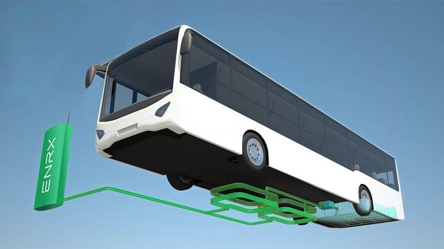
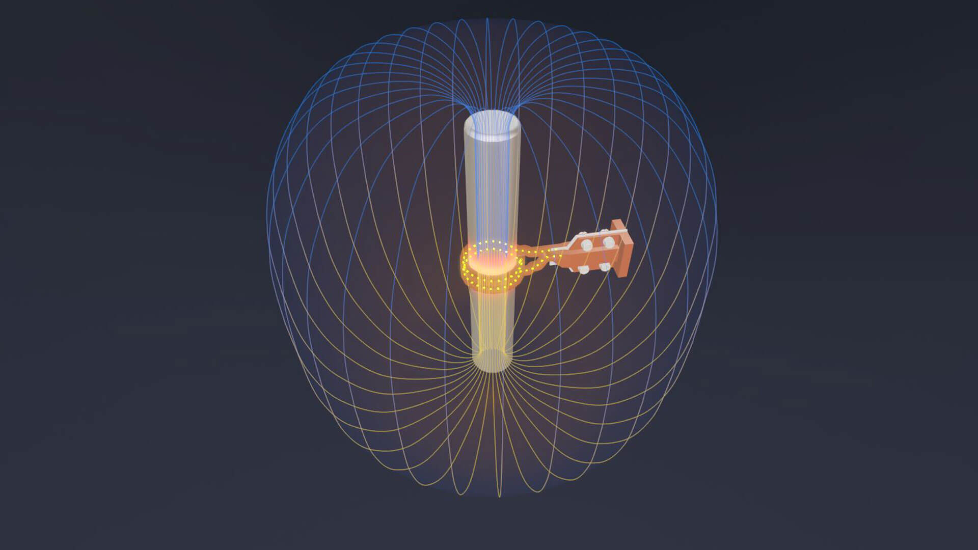
It relies on magnetic induction to transfer energy between a pad on the ground, and another under the floor of a compatible electric vehicle. The charging pad is around a metre square, while the vehicle receiving pad is a smaller, dish-sized device mounted under the car. Once the two are aligned, charging can take place at 1kW – 300 kW speeds.
Wireless energy transfer systems have the benefit of maximum convenience for the driver, as charging is automatic and the system can provide driving assistance. The charging pad is hidden and vandalism-proof. Installation of this “invisible” technology leaves townscapes completely unaffected.
Why is wireless power transfer the future technology?
Because plugging in and mechanical contacts are a weak technology from the past that does not fit to a high level of automation, smart products and ease of use. The advantages of wireless charging are significant. Never deal with any cables, which means vandalism reducing, safety increasing, and nevermore forget to charge the vehicle. In the future, the same inductive charging technology is built into roads (dynamic charging), so cars could charge in transition, making long-distance travel without stopping for charging.
The charger pad could be fully concealed so that it wouldn’t detract from the appearance of the public parking place ore garage, and it potentially could protect the unit from a variety of damage types. This would be the best solution for allowing autonomous cars to fill their energy storage systems.
By eliminating the cables and other wires previously needed to power up electric vehicles, mass transit networks can now blend in with their surroundings. City landmarks, parks and cultural sites are left intact, minimizing visual pollution and enhancing the city’s overall charm.
What are the applications that best suited for IPT wireless charging systems?
Wireless charging is best suited for applications where a high number of charging periods per day are required, such as buses, ferries as forklifts, but also passenger cars, taxi fleets and electric transport.
An additional advantage is that the solution is extremely suitable for the use of harsh climates because wireless charging systems encounter no contact wear and have no exposed electrical contacts.
And inductive charging solutions also save a considerable amount of time because it is a fully automatic procedure where no human interaction is required.
How user-friendly is wireless charging for the driver?
What is more user friendly than a technology that works without the driver having to do anything? Wireless charging is effortless. The driver parks over the charging station and charging the battery starts at the same moment. Simple floor markings, orientation aids or camera systems help with positioning. Charging is no longer noticed at all. In this respect, the process as such is obsolete for the user and can be seen as an increase in user-friendliness.
What about the frequently mentioned disadvantages of wireless charging?
Technology is still in development stage
There have been wireless power supply systems around for more than 20 years now, and they are serial products for everyday use, they are manufactured in thousands and show the highest reliability.
The technology is too expensive
The difference between a plugin or pantograph charger and wireless inductive charging solutions is small. Physically the only thing you add to a wired system is two coils. These two coils add a marginal part of the cost, which is outweighed by the benefits many times.
The efficiency is lower
Our systems show an efficiency from grip connection to a battery of more than 92%, which is in line with conventional plugin or pantograph charging systems. While excellent conductive chargers may reach 95% at nominal power, the overall efficiency in the drive and battery of the vehicle reduces the overall efficiency again. As a consequence, the difference becomes negligible. Additionally, our wireless systems show a very high efficiency over the full range of power levels, while the efficiency of plug-in chargers at power levels lower than nominal are significantly lower. Unfortunately, the numbers are only given for symbolic power and not over the full operational range.
Low charging capacity
Answer: IPT charging systems have a nominal power output of 100, 200 or 300 kW. Wired systems and pantograph systems claim to be at levels of up to 450 kW or even higher.
General
We have to state that most users compare charging with filling up gas at a gas station. The real advantages of electric driving are that you can eliminate the charging process and integrate the power supply into your normal operational process and charge while you use your vehicle. This requires an entirely new way of thinking but offers significant improvements in the overall efficiency of the system.
Additionally, what needs to consider is not peak kW in a given moment, but kWh over a certain time. The energy pushed into a battery is limited by three factors:
-
- The grid connection: Only very few and very costly grid connections are capable of providing power levels of 450 kW and higher for a long time. If you still want to charge at high power, you need energy storage in between that is charged slowly from the grid and discharged quickly via the charging system to the battery. It remains very questionable whether this is an economical solution.
- Battery system: Batteries are susceptible to high charging power. High charging currents above 1C usually reduce the lifetime of the battery. This was the reason why IPT decided to offer a version that increases the lifetime of the battery without losing the performance of your transportation system. If charged with higher peak power levels, the lifetime will be lower. Newer batteries claim not to have this problem anymore, but all research shows that high-speed charging effects on lifetime.
- Charging system: Chargers are designed for maximum peak power or continuous power levels. The information that a given charger can do up to 450 kW does not provide any valuable information. The critical data is how many kWh can you put into a vehicle, considering grid, charger and battery, in, let’s say, 5 minutes. And will the charger be used for only one bus and therefore be rather expensive, or can it be shared by numerous busses and accordingly costs be shared?
An IPT charger is always size at 100% duty cycle, which means if one vehicle has charged for a few minutes, a second one can start charging immediately after the first one, etc. Most of the conductive solutions can do high power peaks for a few seconds and then reduce the power significantly due to restrictions in heat development in the system, grid limitations or battery limitations.
Mechanical conductive systems do need significant time to contact the vehicle properly and retract the contacts, which is not required in a wireless application. A wireless system can start up in milliseconds. If the high power level is not needing in the process and the high kWh are not available, why adding high cost and uncertainty for no benefit?
Also, higher power levels would be possible with wireless technology. The technology is not a limiting factor!
How maintenance-intensive is your solution?
Firstly a wireless solution has no mechanical wear and tear. Secondly, there is no contact surface or pins in plugs that can wear during each contact process and power transfer. Thirdly, accidents due to mechanical damage of the contacts, the pantograph or any other part of the system standing in public can also eliminate.
As these are the main drivers of the maintenance cost, it is reasonable to say that the maintenance of a wireless system will be nearly zero. There is still the need to cool electronics as with all chargers, and the cooling and tightness for water and humidity need to check. But that is a minor effort and also true for all plugin and pantograph systems.
Do you already have long-term experience with it?
The current version IPT Charge 100 kW and 60 kW are very much similar to each other. The technical difference is mainly that the 100 kW version has no lowering mechanism anymore and therefore less maintenance is required.
The first 60 kW system was installed in 2002 and is still successful in operation. In this timeframe, we have supplied spare electronic parts that see some ageing with every switching process, but that volume was low.
For example the system we installed in 2012 in Milton Keynes had no wear parts replaced since it was installed.
How fast is wireless charging compared to plugin or pantograph charging?
The number of kWh determines the charging speed in a given time. Plugin/Pantograph and wireless charging can design to the required level. Typically you find chargers for 3 kW, 7 kW, 11 kW and 22 kW for cars. High-speed chargers can go up to 150-600 kW peak power but limited due to cooling constraints. Unfortunately, manufacturers do not offer values for the kWh in a given period.
Inductive wireless chargers were designed so far for power levels between 3 and 300 kW at 100% duty cycle.
Are you not afraid for hydrogen technology, what will win?
Hydrogen is an interesting technology when it comes to storing excess energy from renewable energy generation. The use of hydrogen in vehicles will make sense for vehicles that need a long-range, which in the end it is maybe 5% or less of all cases.
Hydrogen technology and e-mobility with batteries of continuously powered will not be direct competitors, but both will use where it makes sense and is economical.
Although liquid hydrogen storage has been used safely for many years in secure and regulated industrial sites, its use in relatively congested, highly populated urban areas presents a new set of issues concerning security, safety and associated planning. The Health and Safety Executive commissioned the Health and Safety Laboratory to identify and address issues relating to bulk liquid hydrogen transport and storage and develop guidance for such facilities.
Wireless charging is an expensive solution
When looking at the benefits and the cost of a solution, wireless offers much better performance and features than any other technology at nearly the same price. In that respect, we do not see it as being expensive.
Wireless charging for buses is new for me - is it a reliable technology yet?
IPT® Charge Bus has a long history. Wireless charging applying for the first time with electric shuttle vehicles already in 1998. First IPT® Charge Bus projects were realized in 2002 in Genoa and Turin, Italy. Installations are to date in operation. IPT charged buses had made more than 15 million kilometres already.
What are the advantages of inductive wireless charging compared to pantograph charging?
a) Our system has no moving parts. The coils are permanently installed in the vehicle or in the floor. Therefore, wear due to mechanical movement can be excluded entirely. Accordingly, the maintenance effort reduces to a minimum.
b) The ground coils and power electronics can install separately. This means that no entire concrete shaft has to be sunk into the ground. The power electronics can be installed a few meters away, e.g. as part of the bus stop.
c) When installing separately, the cooling of the power electronics is considerably simplified, so that no separate housing is required. Depending on the location, the integration of an air conditioner is recommending. The monitoring unit also disappears because some components are no longer needed or can accommodate in the enclosure. In this case, the space requirement of our power electronics is also a switch cabinet with a space requirement of approx – 1 sqm.
d) The usual docking process from the pantograph to the bus, until the loading process can begin, is eliminated with our system. A few meters before the bus driver reaches the bus stop, and communication is establishing between the bus and the ground loading system. As soon as the bus driver has reached his final position, the loading process starts automatically and at the same time. This solution saves you valuable seconds that can use for charging.
What is the efficiency of the wireless charging system?
Our wireless charging solutions have high efficiency for more than 92%. Where charging times are low, the losses with wireless charging can be smaller than for other systems. Many factors influence overall efficiency.
Wireless charging is just as efficient as wired charging but offers a host of other benefits. No charging method can show a 100% efficiency. Conventional chargers have an efficiency of 88% to 95%. The wireless version has an efficiency of 90% to 93%. Both technologies work at a comparably high level.
Is the wireless charging system affected by weather conditions, like rain, ice and snow? Our snow is filthy and can also maintain metals.
Yes, even better than with any other charging technology. Snow or water do not influence the charging process, and without any moving parts, the system is not vulnerable to dirt or frozen elements. The Components maintain at the right operating temperature with cooling liquid which is mixed with antifreeze and can heating up at extreme cold weather conditions. IPT® Charge is entirely weatherproof and will work with snow and freezing temperatures as well as with lasting heat waves.
Is the wireless charging system affected by weather conditions, like rain, ice and snow?
Yes, even better than with any other charging technology. Snow or water do not influence the charging process, and without any moving parts, the system is not vulnerable to dirt or frozen elements. The Components maintain at the right operating temperature with cooling liquid which is mixed with antifreeze and can heating up at extreme cold weather conditions. IPT® Charge is entirely weatherproof and will work with snow and freezing temperatures as well as with lasting heat waves.
Our snow is filthy and can also maintain metals.
If snow contains small metal parts, these metal parts will warm up in the electromagnetic field between the coils. It will cause the snow to melt. Also, the heating of the metal parts will reduce efficiency slightly.
We suggest cleaning the surface of the pad from these metal parts to reduce the losses and to avoid hot objects laying on the ground after the charging process, even though the objects will cool off very rapidly.
In case of a non-supervised charging process in public, a metal detection system should be part of the offer to avoid any risk of hot objects causing burns on humans, if they touch the objects when it’s still hot.
Is the ground unit ready for chemicals to keep snow away?
The ground is made of a material that is resistant against “normal” chemicals used in public applications, e.g. salt. They are also resistant against temperature changes, humidity, UV radiation from sunlight that can expect outdoors.
Does the wireless charging system also work with leaves or snow on the road, i.e., does it have to be removed or can it remain in place?
An IPT wireless system will always design to cope with the normal behaviour of a user and environmental conditions. This also means that the design deals with high and low temperatures, snow, ice and winter as well as conditions we find in fall when leaves cover the ground.
Additionally, the significant benefit of wireless charging is the fact that non-ferrous-magnetic material does not affect the power transfer at all. Leaves, water, ice and snow are such materials.
What is the impact of wireless charging on the battery?
A wireless charging system has a no different effect than any wired connection. When it is used in an opportunity charging application, then it has a positive impact on the lifetime of batteries. As in these cases, charging happens slower and in the medium charge levels between 40 and 80%. Both effects are positive on the lifetime of batteries.
Typical Li-ion batteries show the following characteristics:
Courtesy: ResearchGate – Modeling of Lithium-Ion Battery Degradation for Cell Life Assessment.
Source: Choi & Lim – Journal of Power Sources
Is IPT wireless charging designed for specific battery types?
IPT® Charge is designed to charge a wide range of different batteries. You may look at it as a wall socket. Whether you connect a vacuum cleaner or a TV-set, it makes no difference. The solution leaves the charging management always to the vehicle and adapts to the requirements from there. Communication inside the vehicle uses standard CAN-based interface.
Are the buses currently equipped with wireless charging also charged overnight wireless or via a plug-in station?
The projects we realized so far were done with partners that insisted on the redundancy of systems, which lead to the fact that all buses are equipped with plugin chargers and wireless charging capability. This is understandable when using a technology for the first time, but not necessary. Overnight charging and balancing of batteries can also done with a wireless system anywhere and of course even in a depot and overnight at low power levels.
Must the charging coils be parallel, or is it possible even if the vehicle kneeled? What if the air gap is larger than 15cm? Will there be no - or reduced energy transfer?
The parallelism of the coils does not have to be guaranteed. The kneeling does not influence the transmission performance and can take place without hesitation. We can realize air gaps of up to 25 cm and more without any loss of performance.
Our system design is to transmit full power levels in a reasonable range of tolerances to be expected. Beyond this point, we reduce power transfer gradually for safety reasons and switch it off, when positioning is far from expected values. This also includes tolerances for angles in all directions. A detailed description is available for the 100 kW charger.
What is the weight of a system for the bus?
The charger components that additional installed in the bus weigh approximately 200 kilograms. Good to know is that the battery capacity of the bus can significantly reduce by using en-route opportunity charging.
How accurately do you have to stand above the plate by the vehicle? How much distance tolerance is there if you are not entirely above it?
The system design is that the bus driver can move the charging pad within a specific tolerance range. The tolerance field is approx. 15 cm in x- and y-axis – without any loss of transmission power. Transfer of energy is always possible based on more tolerance, but we advise a maximum deviation so that charging will not become inefficient.
Do you charge AC or DC?
Our developments assume that the most efficient connection point in the vehicle is the battery. As batteries use DC, this is what we provide. Battery voltages can vary depending on how they built and what cell types there are using. Usually, you find:
- 12 V, 24 V, 80 V as voltages for small vehicles and small industrial applications
- 300-400 V for cars and 600-750 V for heavy vehicles and high-performance cars
What communication are you using?
We communicate through a modem between charger and vehicle, but we could use any other reliable and cost-efficient means of communication.
What about the possible effect on pacemakers and other EMF health concerns?
When designing the wireless charging solutions and testing of magnetic fields involves levels that apply to the general people all the time. And this is well below the expectation to affect persons with pacemakers and other EMF concerns. Advice from suppliers of the devices should be following.
Bundesamt für Strahlenschutz refers to limits of 2,5 mV/m or 20 μT (Microtesla).
Pacemakers and other electronic implants have to show that they work safely up to these limits as a minimum. The recommendations from the International Commission on Non-Ionizing Radiation Protection (ICNIRP) are 6,25 μT (Microtesla) form 1997, and respectively they were raised to 27 μT (Microtesla) in 2010. These limits are for continuous exposure.
The fields measured at any point accessible by a person for our IPT systems were always in the range of 1,5 – 3,5 μT (Microtesla). For every application, we do measurements of the levels and provide them to our customers.
What is the impact for a living being?
A wireless charging system works with a frequency between 20 and 140 kHz. These frequencies can, therefore, be considered low-frequency fields. Such frequencies at a certain level have neuronal and muscular effects just like fields in a living being that are natural fields generated by the body itself.
High-frequency fields can cause heating of human or living tissue similar to the heat generated through muscle contraction. Relevant for effect is frequency, field strength and duration of the exposure. While the results described above can see, it is unclear whether exposure for a short time has any effect at all. Still, to be on the safe side, we have decided not to accept any exposure of the full electromagnetic field to any living object.
Measurements show that the field generated by IPT® Charge is by far within the limits of the reference levels of the International Commission on Non-Ionizing Radiation Protection (ICNIRP).
Table from Bundesamt für Strahlenschutz (DE)
Generally and contradictory to an antenna, our wireless systems design in a way that nearby between the coils, there is an electromagnetic field that allows power transfer. Still, in the low distance, the alternating fields eliminate each other, and thus the electromagnetic fields are minimized or not present at all. Also, the coils act to the outside as shielding against electromagnetic fields. The vehicle also acts as a shielding.
We have to distinguish between applications that are supervised by a driver, where we can assume that the system will not be activated unless the coils are free from any living creature or human. Otherwise, the likelihood of running over the animal or human with the vehicle itself is the most risk. For these cases, we can assume that the area below the vehicle is free from any living object.
Applications without supervision, e.g. a charger in public space, where the car user has left the vehicle in parking, is the second option. In this situation, the charging happens automatically, and a creature could access the space between the two coils while it is active. Then, we ensure an electromagnetic field that is always below the value of 20 V/m or includes high sensitive detection of living creatures by movement – assuming that any living creature will move in the electromagnetic field.
Applications without supervision, but in an enclosed area, like a fenced company parking with no public access is the third case. Here we can assume that information about all visitors walking freely on the premise can be a good measure to avoid any unwanted exposure.
Of course, mandatory, that electromagnetic fields next to and inside the vehicle stay clear within the given limits. As you can see above, these limits remain clearly within the levels, which a reasonable being through its existing natural fields would expose to anyway.
With typical air gaps of 150-200 mm, it can additionally assume that an average person would not be able to crawl into such a field.
Pacemakers and other electronic implants can be affected at levels lower than the standard mentioned above. “Bundesamt für Strahlenschutz” here refers to limits of 2,5 mV/m or 20 μT (Microtesla).
Pacemakers and other electronic implants have to show that they work safely up to these limits as a minimum. The recommendations from the International Commission on Non-Ionizing Radiation Protection (ICNIRP) are 6,25 μT (Microtesla) form 1997, and respectively they were raised to 27 μT (Microtesla) in 2010. These limits are for continuous exposure.
The fields measured at any point accessible by a person for our IPT systems were always in the range of 1,5 – 3,5 μT (Microtesla). For every application, we do measurements of the levels and provide them to our customers.
Infrastructure & standardization
What is opportunity charging?
Opportunity charging is a technical term used for describing the way of en-route charging. The usual thought is that a vehicle needs to be taken out of service for charging, just like it is for filling up on a gas station. During the charging time, the vehicle can not serve its purpose because it is out of service.
With e-mobility and an automated charging process, you can integrate the charging process into your usual mode of operation by installing chargers where the vehicle has to stop anyway or by charging while driving. On the one hand side, this requires a defined process of operation, that is most of the times the same, but on the other hand, increases the availability of your vehicle significantly and makes the whole operation more economical. It eliminates the charging time. You probably need fewer vehicles, or you can increase the service time.
To boost the profitability of a bus fleet, it is not just about having the right drive-train: you also need the right charging technology. Fleet operators can save a lot of money by buying buses with smaller batteries in which the cell chemistry is kept healthy by more-frequent, but shorter charging cycles, which means that the cells have a longer service life. With the operational concept of en-route opportunity charging, less weight needs to be carried around, and no special journeys back to the depot are required. Opportunity charging has a significant effect on the overall cost and system efficiency and that the maintenance costs are considerably lower.
What are the advantages of inductive wireless charging compared to pantograph charging?
Our wireless charging system has no moving parts. The coils are permanently installed in the vehicle or in the floor. Therefore, wear due to mechanical movement can be excluded entirely. Accordingly, the maintenance effort reduces to a minimum.
The ground coils and power electronics can install separately. This means that no entire concrete shaft has to be sunk into the ground. The power electronics can be installed a few meters away, e.g. as part of the bus stop.
When installing separately, the cooling of the power electronics is considerably simplified, so that no separate housing is required. Depending on the location, the integration of an air conditioner is recommending. The monitoring unit also disappears because some components are no longer needed or can accommodate in the enclosure. In this case, the space requirement of our power electronics is also a switch cabinet with a space requirement of approx – 1 sqm.
The usual docking process from the pantograph to the bus, until the loading process can begin, is eliminated with our system. A few meters before the bus driver reaches the bus stop, and communication is establishing between the bus and the ground loading system. As soon as the bus driver has reached his final position, the loading process starts automatically and at the same time. This solution saves you valuable seconds that can use for charging.
What are advantages of wireless charging vs overnight plugin charge
Wireless charging is an alternative to plugin charging and can be done as opportunity charging during the day as well as overnight.
Plugin charging is usually only done overnight. For opportunity charging a driver would have to exit the bus and plugin during operation, which is not a practical solution.
Overnight charging concentrates the charging process between midnight and 5 am typically, and it focuses the charging process to a place that the bus operator usually owns, the depot.
The advantages are the fact that charging happens in a controlled environment and during a time where electricity is usually cheaper.
A disadvantage is that you need to charge all vehicles at the same time and the batteries are usually rather empty when entering the depot. You need a vast and costly grid connection, you need more space than with conventional vehicles due to the many chargers installed and the lifetime of the batteries will be affected due to the full charge/discharge cycles that come with it.
In contrast to that, opportunity charging with pantographs or wireless solutions have the disadvantage, that equipment has to installed in places, that may be the property of a third party, and therefore installation is usually more complicated.
The significant advantage is that you spread your power consumption over the whole day and the entire city. Which makes grid connections considerably cheaper and also the vehicles are always charged. You could even sell your depot as it is no more needed. You’ll need a small place to clean and service the vehicles and theoretically operate 24/7.
Cost for pantograph and wireless solutions are somewhat comparable, whereas pantographs still have a substantial unsightly mast and mechanical contacts.
What do we need for Infra, how does this compare to conductive?
On the Infrastructure side, a wireless charger requires a grid connection, has a wall box (power electronics) and a coil.
When installed and used in public, it would, of course, have to be according to standard and have an OCCP connection.
For higher power above 22 kW and other arrangements, the system may have been built in-ground, which requires the agreement with the owner of the land and making sure that the ground is free from other equipment (phone, gas, water pipes, etc.)
Can buses of different sizes and widths - or even other vehicles - share one charging station?
A charger always needs a suitable counterpart. For the existing 100 kW system, the secondary side needs to be a 100 kW pick-up coil arrangement. Once installed on different vehicles of identical or different size, the same infrastructure can be shared by those vehicles.
In the future, we also see that one infrastructure may be able to serve different power levels on the vehicle side.
What if due to adding more electric buses the chosen initially 100 kW is no longer sufficient?
If the power of 100 kW is sufficient for one bus, there is no reason why it should not be enough for many of them as the charger is designed to work 100% of the time. If additional busses are much bigger and require more charging power, then a second and even a third charger can be added to get up to 300 kW, so the system is scalable.
Which components exactly have to install inground, and what are the dimensions?
The present system design is to put as much equipment as possible underground because one of the benefits of wireless is that it does not need anything visible.
It is not a technical requirement of the technology itself. We have already offered variations, where only the coils or the coils and parts of the power electronics are below ground. These can also be separated, to have only part of the system on the road, part of it on the curbside.
We have also considered using multiple coils with one big power electronics unit, e.g. for depots. These coils could make smart to provide just the power needed for each coil and have an intelligent balancing of the loads and control to limit the load on the grid side.
What is the volume of your monitoring unit? Are there any noise results for this control cabinet?
Sizes are (LxWxH): 1m x 0.6m x 2m.
The monitoring unit consists of the main fuses and grid connection plus a PLC unit controlling all functions of the system. The PLC unit is usually connected to a modem. The cabinet has temperature sensors and a ventilation system in case of too much heat in the cabinet. If the fan is active, it makes a low level of noise. At a distance of 2 meters, we are without enclosure at a noise level of 65dBa.
What is the expected operational life of the equipment?
The equipment is designing to operate for at least 15 years. With the right maintenance, it may function even longer. IPT will continue to support the system design. Some upgrades to the system may be needed to compare to the latest technology. IPT has been showing for more than 17 years how well inductive charging of batteries can work in the context of local public transport: there are about 30 electric buses in Genoa and Turin that have been using IPT wireless technology since 2002. Seventeen years on, the Italian public transport companies AMT and GTT are in no doubt about the success of the application of this technology under everyday conditions. The buses in Turin reliably travel 200km a day without needing to stop anywhere for a prolonged period or having to return to the depot for charging.
In which case would the installed Monitoring Module have to be opened?
In regular operation, an opening of the Monitoring Unit is not necessary. The possibility of remote maintenance enables good transparency of the operating parameters. It needs to open if a fuse breaks or the CPU fails. Everything else is possible to check remotely. If errors cannot be solved by remote access, an inspection must carry out on-site, and the switch cabinet should be opened.
We don't always have stopping edges to orienting ourselves. Sometimes there are just open places where we stop.
Positioning can become in several ways:
- Visual positioning by the driver: This is the solution mostly used as drivers have a perfect understanding of the position, no matter if it is an open place or on the side of a road. There are always point for orientation.
- Camera systems and markings on the road: These systems are very accurate and reasonably cheap. Unfortunately, they do not work when the charger is covered with snow or leaves. Our experience is that they work fine. Snow, ice and leaves are a problem in very few cases like winters in Nordic countries. Additionally, we experienced that drivers stop using these systems after a short time as visual positioning is good enough.
- Triangulation systems with transponders/senders in the ground and receivers on the vehicle. These systems work but show some weakness in reliability as signals are subject to conditions between the sender and receiver unit. Steel and metal structure cause reflections that make such systems less accurate. Additionally, they only work in a certain proximity of a few meters. We have not realized a system yet as it is quite costly and has the weaknesses described.
- Use the GPS/positioning of the vehicle: Today, many vehicles already have a GPS positioning, which can use for positioning. So far, it has not implemented, but we believe that this will be the perfect solution. The advantage is clear: no additional cost for a system, that is already there.
Can we use one controller unit for multiple primary coils?
That is possible, we have also developed concepts and would be happy to realize it, but it is not yet an off-the-shelf product.
Is it OCPP 2.0?
For payment processes during charging a protocol is developed to allow for correct identification of the user of the charger (via RFID Chip or Credit Card), transfer the exact amount of energy consumed and the amount to pay. This is a device that would have to be added to our charger in case it is used for public charging of electric cars.
While this is technically not a problem for us, it has not been a real issue so far as there are not standard cars with wireless charging available. No public charge points installed for wireless charging and there is no final standard for interoperability of wireless charging systems available yet.
OCPP 2.0 is, therefore, not an issue so far. All systems provided are proprietary, and so billing is not an issue yet.
Is it ISO 15118 ready?
ISO15118 is a communication standard between vehicle and changer. So far, it is only defined for plugin chargers – where additional safety pins in the plug make sure that the charging process is safe.
For wireless charging, we also use a communication protocol that is similar to ISO15118, but wireless charging needs to let safety communication as a plugin charger. There are ongoing discussions to include wireless into ISO15118, and this will soon be the case, but not yet.
Can it do V2G? Can I sell energy to others?
V2G is the next step in standardization, but will not be available in the coming years. For proprietary systems, it may be available sooner as interoperability is not needed.
Can our charging systems be retrofitted?
Yes, our system can be installed by any manufacturer. It’s developing for quick retrofitting. We have already retrofitted existing monitoring units with the latest CPU and modem technology. Whether or not our components are planned into the design and planning process of vehicle development right from the start is irrelevant to us. We have design the system so that it can easily integrate at any time to remain as independent and flexible as possible. What has to take into account is that the ground clearance of the vehicle changes during retrofitting.
If problems arise, how can access grant? Does a crane need to open the cover of the sunken box or what are the possibilities?
In case of problems, the following scenarios are usually followed:
- An error message is flagging by sending a message to IPT and the operator
- An error is interpreted and checked remotely: most of the mistakes can solving remotely.
If an error can not be solved remotely, most times it has to do with the cooling unit, that can be serviced without having to open the ground unit.
If the error is in the ground unit, then there are three options:
- Lifting out the ground module and replace with a spare unit, analyze and repair in a workshop. For this, you need a crane (6t) and around one hour. The charge point is back in service immediately.
- Lifting out, analyze and repair at the site. This is the solution when the user is not having a spare unit. Working on electronics in an unsafe, dirty and possibly wet environment is not recommended. The duration can go from 1-2 hours up to 3-4 days. The charge point is out of service for the duration of the repair work.
- Lifting out, replace with blind cover, analyze and repair in workshop. This will be the solution when the user doesn’t have a spare unit but has a blind cover. Charge point will not be operational for the duration of the repair work. The period can go from 1 to 4 days.